| Modification 4: Power Options
Many users wish to power their practice beacons by something
other than the batteries provided by
Pointer. Please
note that doing so will void your warranty!
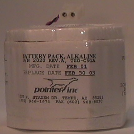
The original battery supplied by
Pointer is a "real" ELT
battery and will therefore have an expiration date. The
original battery is
Part Number 2020, and costs around $25 - $35 US. You
will find that this battery will generally last a long time.
Additionally, the supplied alkaline battery pack specifically
designed to endure short term extreme thermal variations and
mechanical shock. The bottom line is that it is a good
battery, but is expensive over the long haul. Since it is
usually much easier and cheaper to pick up batteries from your
local retailer, modifying your beacon to use a different power
source may be for you.
There are a great number of options available to power your
beacon. If you wish to have a new battery, another ELT
manufacturer makes batteries for
Pointer ELTs. The
manufacturer is
Artex, Inc., and the part number is
00-30-006.
A very good option is to use expired batteries for real ELTs.
ELT batteries must be periodically replaced by an aircraft
maintenance technician. If you ask around at your local airport's Fixed Base
Operator (FBO), the mechanics there may be willing to donate the
expired batteries that they remove from actual ELTs. Providing they are the same
type, they will work wonderfully in your Practice Beacon. It shouldn't
take too much convincing for the FBO since they would throw these
batteries away otherwise. In fact, they likely will not have any
lying around and will have to specifically save them for you.
Please note that if you are disposing of ELT batteries in bulk
that they are considered hazardous waste and need to
be disposed in an environmentally friendly way (by law).
 If
you use the battery supplied by
Pointer or another ELT
battery, you will not be able to modify the power output of the
beacon. Pointer
even talks about home-made battery packs and some of the options
you might want to consider on their
Pointer 6000 web
page. This short page also discusses the
frequency reassignment that was required more than a decade ago.
In summary, it states that in designing a power source you
should use 8 volts maximum. At 7.5 volts, the
nominal power output of the beacon will be 150 milliwatts.
The original batteries supplied by
Pointer test at 7.5
volts as well. You might wish to note that by
specification the power output of most ELTs is 100 milliwatts (TSO
C-91 and C-91a beacons ELTs), and 25 milliwatts for 406 MHz ELTs
(TSO 126). To simulate a beacon that is transmitting at
low power, Pointer
suggests using a 6 volt power supply. They further suggest
that you can shorten the telescopic antenna to simulate a broken
antenna. If
you use the battery supplied by
Pointer or another ELT
battery, you will not be able to modify the power output of the
beacon. Pointer
even talks about home-made battery packs and some of the options
you might want to consider on their
Pointer 6000 web
page. This short page also discusses the
frequency reassignment that was required more than a decade ago.
In summary, it states that in designing a power source you
should use 8 volts maximum. At 7.5 volts, the
nominal power output of the beacon will be 150 milliwatts.
The original batteries supplied by
Pointer test at 7.5
volts as well. You might wish to note that by
specification the power output of most ELTs is 100 milliwatts (TSO
C-91 and C-91a beacons ELTs), and 25 milliwatts for 406 MHz ELTs
(TSO 126). To simulate a beacon that is transmitting at
low power, Pointer
suggests using a 6 volt power supply. They further suggest
that you can shorten the telescopic antenna to simulate a broken
antenna.
If you're still reading this and your eyes haven't glazed
over, you likely already know that a fresh AAA, AA, C, or D cell
alkaline battery supplies approximately 1.5 volts.
Therefore, for a 7.5 volt battery back you will want to use 5
batteries in series. For a 6 volt battery back you would
want to use 4 batteries. Rechargeable batteries (such as
Ni-Cads) typically output 1.2 volts apiece, so adjust your
planning accordingly (5 x 1.2 = 6.0, 6 x 1.2 =7.2). Of
course, D cells will last longer than the other types.
D cells may also be more likely to give sufficient voltage in
cold weather. D cells can be rapidly replaced, are readily
available just about anywhere (such as the gas station at
midnight), and are small enough that you should be able to fit a
spare set inside of an ammo can setup.
Begin by unscrewing the back panel. Use a
voltmeter to ensure the polarities between your battery pack and the original
battery match. If you improperly
connect the wires, you will damage the practice beacon. Of course, you should be
able to determine positive and negative terminals from the way the
original batteries are shaped. It is always better safe than sorry,
though, so run the voltmeter.
At this point you have several options. They are:
Option 1: Keeping the battery pack inside of the beacon
housing
Using this option allows the most portability of the beacon.
Externally the beacon will be identical to a new beacon as
shipped from the factory. This will allow for the easiest
use as well. A battery holder for AA batteries will fit
inside the case. Unless you fabricate a battery pack as
shown below, that is just about the only option (excluding, of
course, the standard p/n 2020 battery from Pointer).
Option 2: Place the power source outside the beacon housing.
This is the most common option. You will need to solve
several problems for this to work well. First, you will
need to determine how you will run wire from inside the beacon
container to your battery pack. You will probably have to
drill a small hole in the casing of the Practice Beacon to admit
the wires. This will compromise the waterproof seal of
your practice beacon, so liberally apply hot glue or another
sealant if this is important to you. You could also mount
a barrel-style power adapter that can connect directly to the
beacon. For example, Radio Shack part #274-1563, "DC Power
Jack, panel mount, Size M." You will be able to find the
electronic components listed on this site at an decent
electronic parts house, to include internet catalogs.
Radio Shack part numbers are included because a Radio Shack
store can be found nearly anywhere in the nation.
Option 3: Keep a battery pack inside the beacon while
allowing for an external connection for power or charging
This option allows the practice beacon to run off the internal
battery when disconnected from external power and also has an
external adapter (as described in the Option 2) to allow for
charging OR to power the beacon, depending on your design.
The CAP Emergency Services Resources™
website is aware of a modification that allows a user to plug in
virtually any low DC voltage (6 - 35V) to power the beacon and
also automatically isolates the battery. This information
will be provided as it becomes available.
Since your battery pack is outside of the beacon for options
2 or 3, you will need a method of keeping everything together.
An excellent idea is to construct a
Practice
Beacon Box from an ammo can as outlined on this site.You
must also choose what will power your beacon. In addition
to AAA, AA, C, and D cell batteries, you may also use a 6 volt
lantern battery. The advantage of this battery is that you
only have to deal with the single cell and you don't need a
holder.
Speaking of battery holders, if you wish to use the 5 D-cell
configuration, you would probably like to know that Radio Shack
carries battery holders for most battery sizes. For
example, a single D Battery Holder: Radio Shack Part #270-403
and a 4D Battery Holder: Radio Shack Part #270-396.
Arrange multiple holders in series (if required).
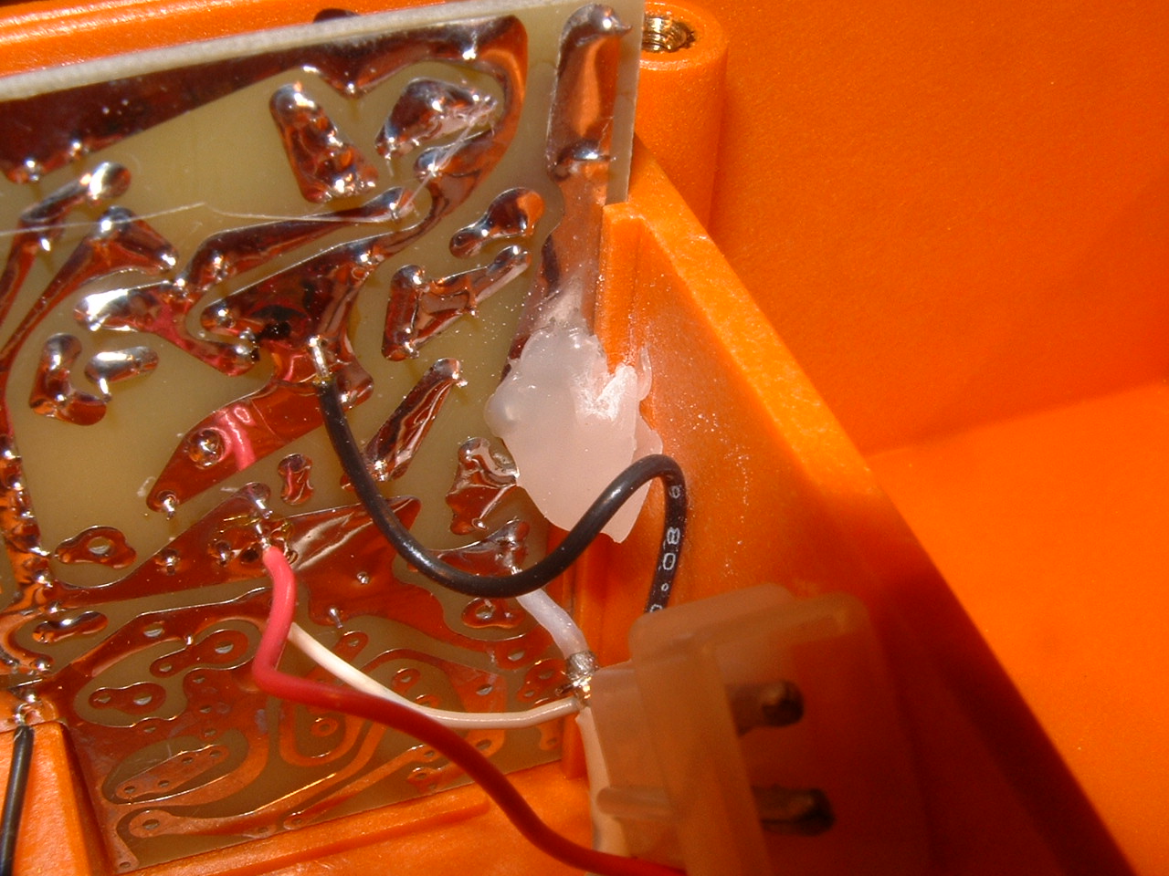
Run the wires from your battery assembly to the Practice
Beacon. If they are not long enough to mount them in
the box, add additional wire. You can use the molex-style wire connector
from the old batteries to the new standard battery holder. This
facilitates easy swapping of battery packs.
When complete, you will wish to secure the battery pack
inside your beacon box. Hot glue or velcro are good
options.
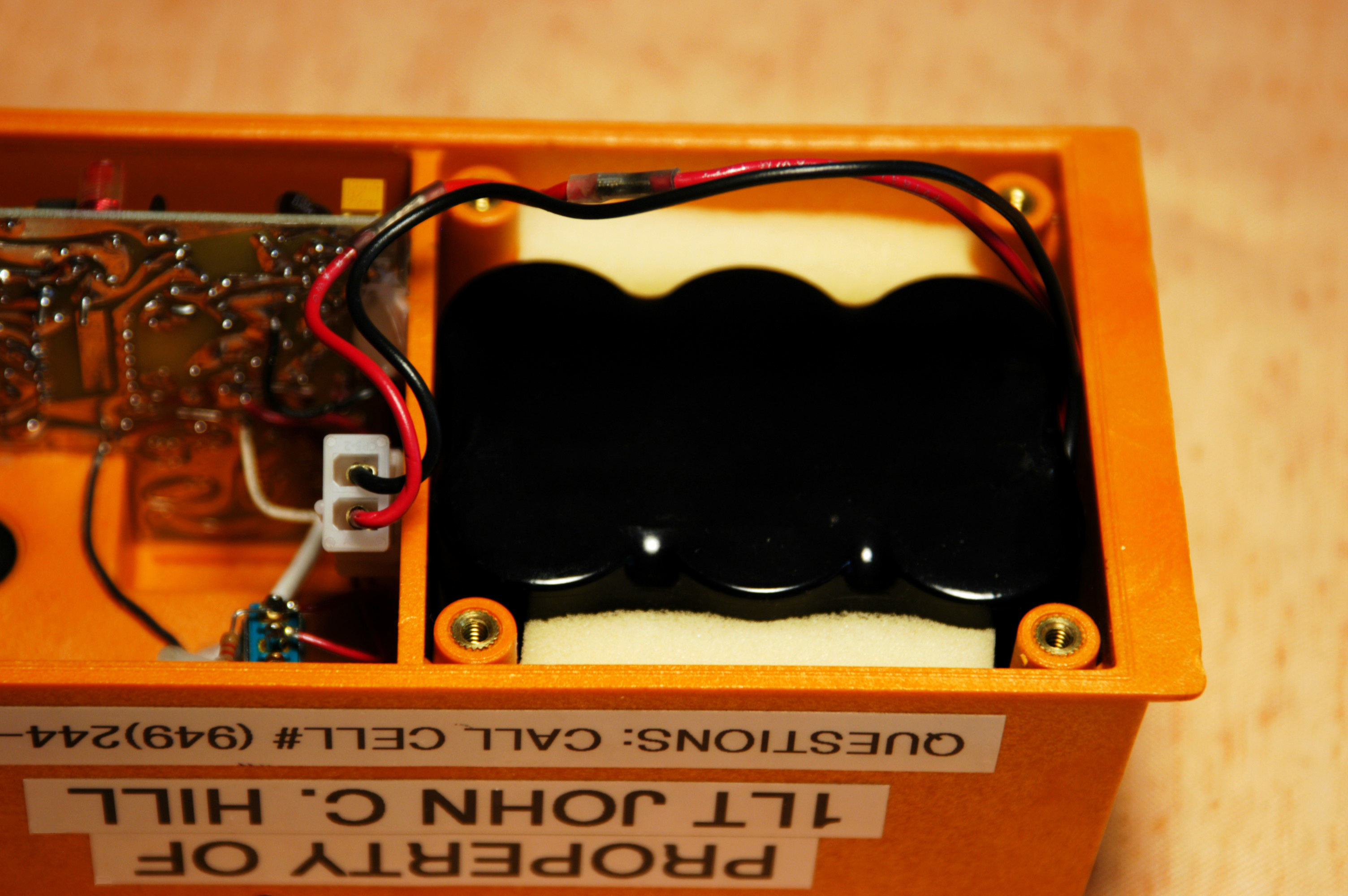
The following is an excellent example an elegant solution
using rechargeable batteries. This information was
submitted by 1Lt John C. Hill, CAWG Group 7 ES Officer.
Many thanks, John, GREAT WORK!
The battery pack consists of six(6) SANYO N-3000CR "C"
cells. These are 1.2 volt NiCAD batteries that,
connected in Series, add up to 7.2 volts.
The Series Connections between batteries are thin metal
straps that are spot welded in place. Any battery pack
company (for example, "Batteries Plus") will be able to do
this spot welding using a desktop welder. This machine
is only about the size of an espresso maker. Welding
should cost about $5. That should also cover
professional soldering of the pigtails, and application of
heat shrink wrapping of the whole assembly. Including
the cost of the batteries, the whole thing will end up
costing about $50. There is no performance data yet
for how long the beacon will last between charges.
The molex-style battery connectors can be found in an AMP
618-2 package. This package contains two (2)
male/female and socket/pin pairs. You might end up with more
connectors than you need, but they're cheap. The
package is identified as TYCO / Electronics, AMP, General
purpose Connectors, 2 Position Free-hanging 20-14 AWG, And
is distributed by GC/Waldon. There are two Part
Numbers on the back, AH1680 and 05165. Your local parts
supply house or an AMP catalog will yield the individual
male connector and sockets required to mount to the practice
beacon. Currently the beacon must be opened to recharge
the battery pack, but 1LT Hill is working on an external
connector as described in the options above. This will
allow an external charger to be plugged into the POINTER
6000 without having to take it apart. A MAHA 777+
charger could be plugged into the power connector or even a
standard wall-cube type module power supply. Isolation
of the battery for charging is being examined.
Note the close fitting of the battery pack in the photo
above. Also note the nice detail of adding the foam to
stabilize the battery pack.
|
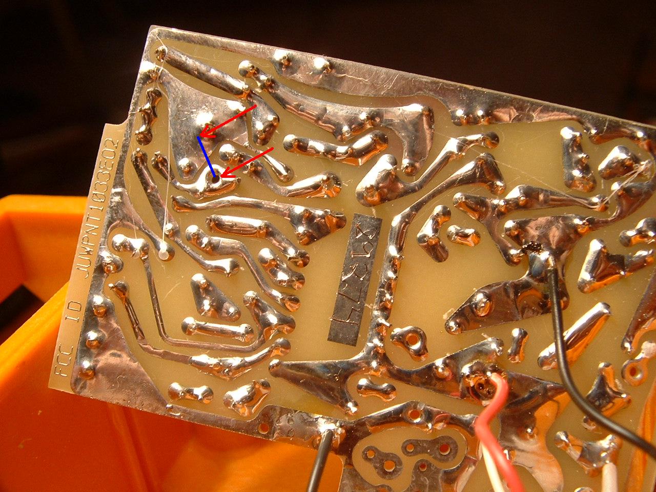
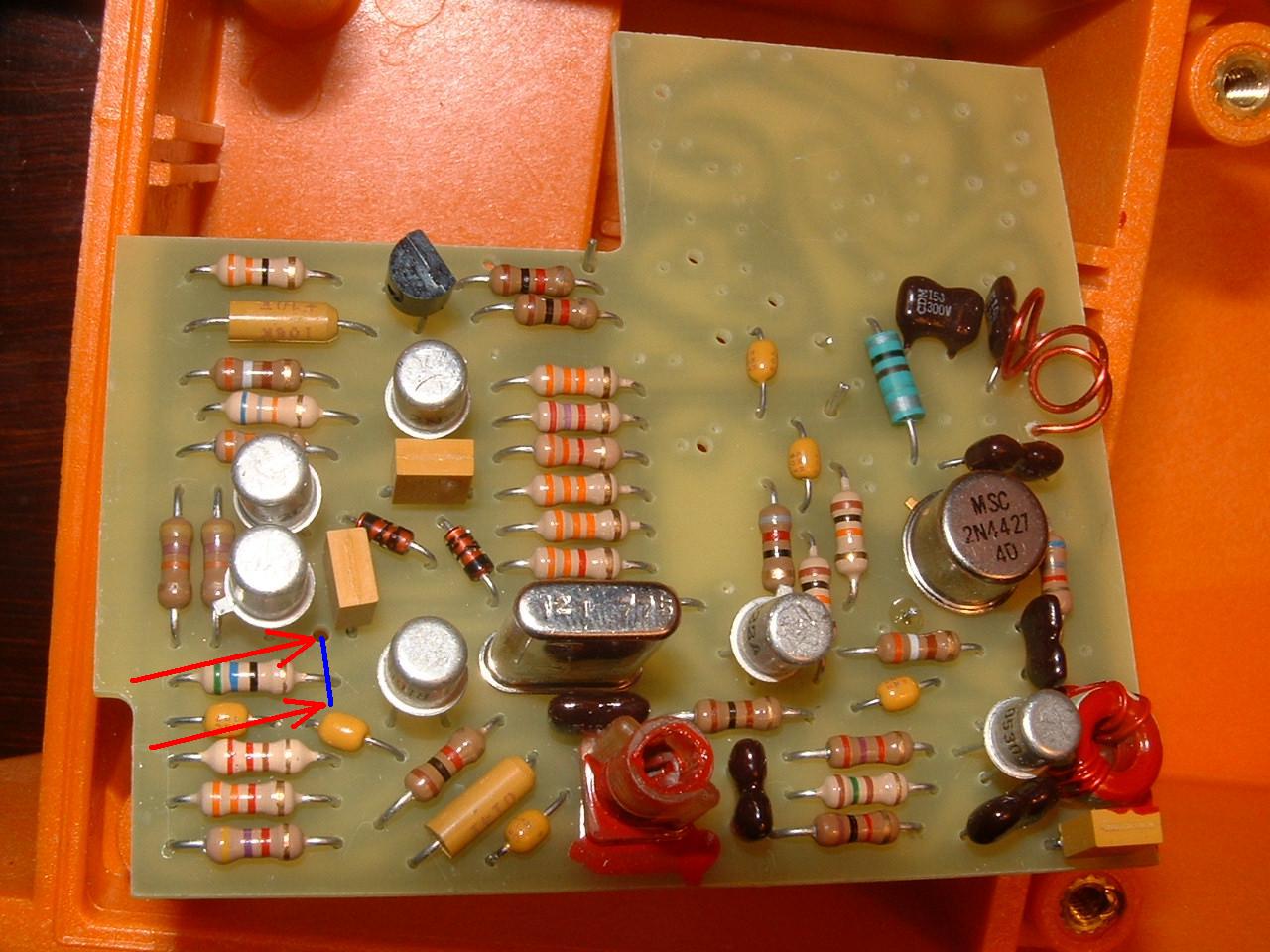
 Step 5.
Next
you will need to solder wires to each of the short points.
I chose to use yellow wires for clarity. You can see my
less-than-perfect soldering job here. You must be careful
not to let any extra solder to accidentally bridge any points on
the back of the board. You can see that there are many
places where the circuits are close together. This is one
of the places where you can do permanent damage to the beacon.
Be careful!
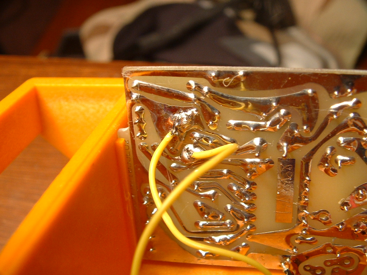
Step 5.
Next
you will need to solder wires to each of the short points.
I chose to use yellow wires for clarity. You can see my
less-than-perfect soldering job here. You must be careful
not to let any extra solder to accidentally bridge any points on
the back of the board. You can see that there are many
places where the circuits are close together. This is one
of the places where you can do permanent damage to the beacon.
Be careful!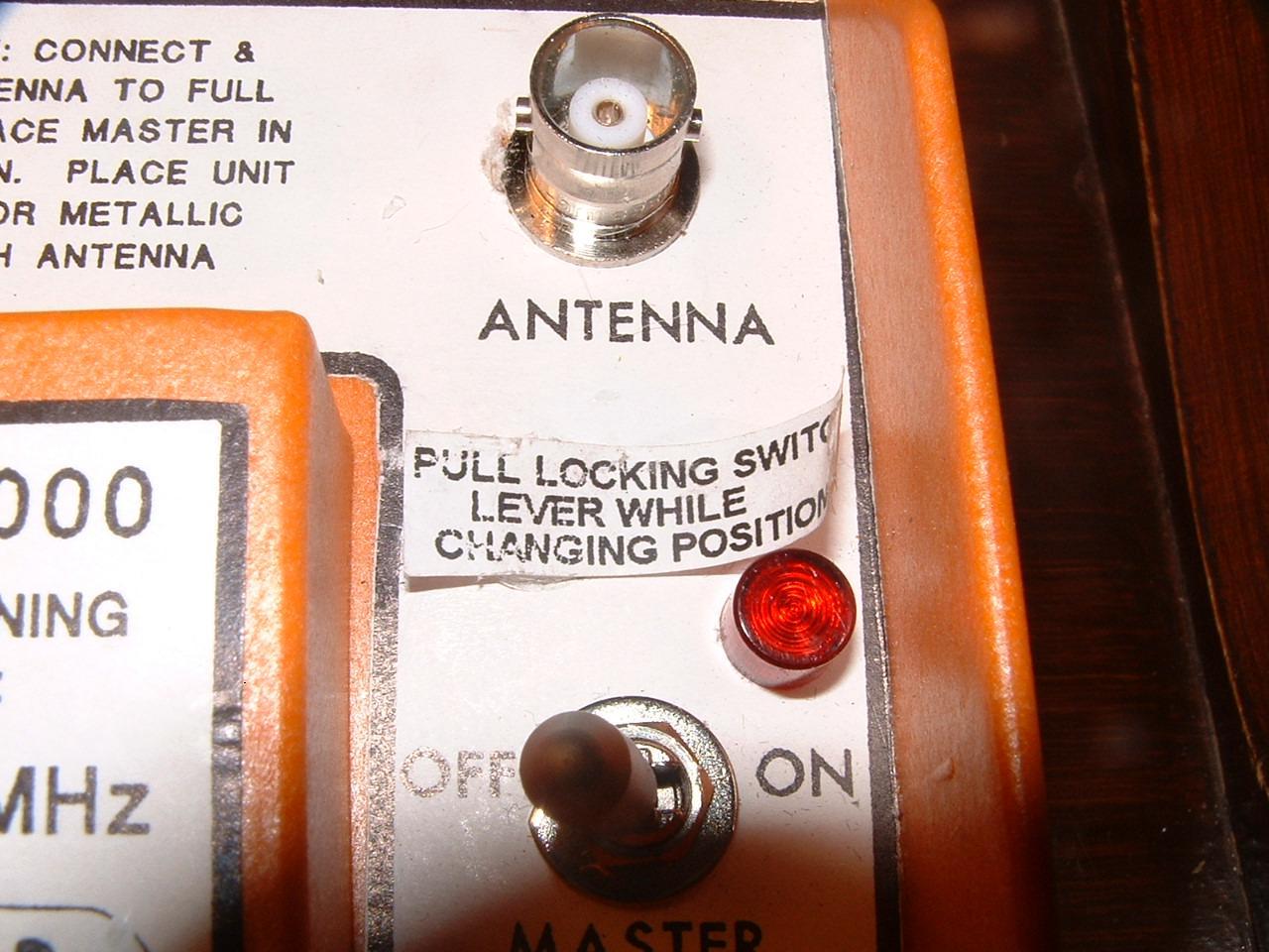 Step 6.
Because
you will want to be able to select whether or not you wish to
hear the sweep, you will most likely want to install a switch
between the two points identified in the previous step. A
closed switch will short the points and disable the sweep.
And open switch will allow the practice beacon to operate
normally. The complexity of your switch is up to you--you
could even just leave the two wires inside the case and open up
the beacon every time you wanted to change operating modes.
If you have a recent beacon, you will want to carefully remove
the label. Here you see the label loosened up so that its
ready to pull off.
Step 6.
Because
you will want to be able to select whether or not you wish to
hear the sweep, you will most likely want to install a switch
between the two points identified in the previous step. A
closed switch will short the points and disable the sweep.
And open switch will allow the practice beacon to operate
normally. The complexity of your switch is up to you--you
could even just leave the two wires inside the case and open up
the beacon every time you wanted to change operating modes.
If you have a recent beacon, you will want to carefully remove
the label. Here you see the label loosened up so that its
ready to pull off.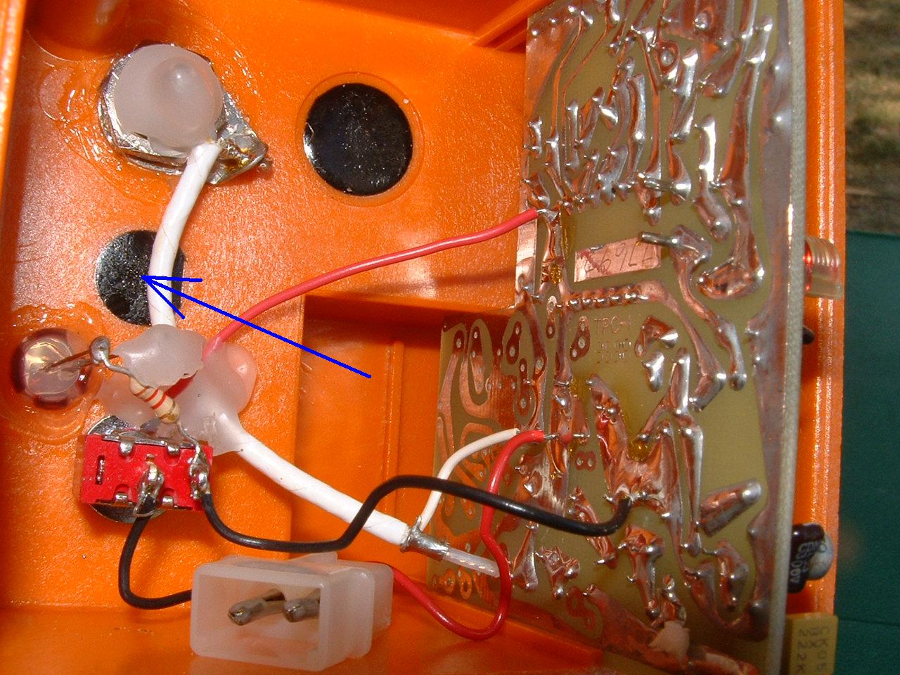 Step
7.
Drill
a hole large enough to mount your switch. I chose to use
the black spot you see highlighted here. This is actually
used for a port or a switch on the "real" models of the
Step
7.
Drill
a hole large enough to mount your switch. I chose to use
the black spot you see highlighted here. This is actually
used for a port or a switch on the "real" models of the
 Step
8.
Here
you can see what the switch looks like from the front. I
chose to arrange it so the switch is shown in the closed
position. This way it conforms to the convention of the
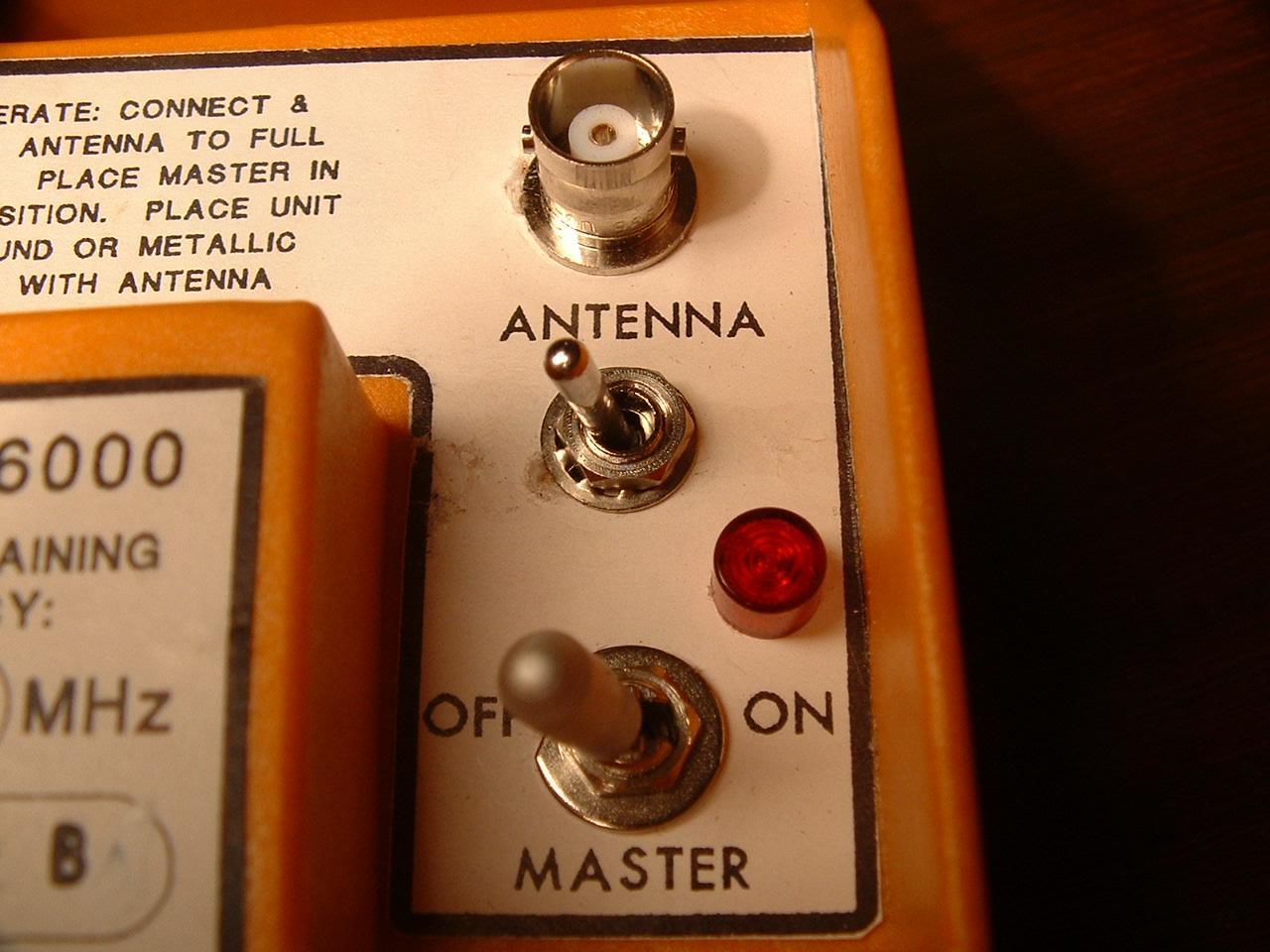
master switch, seen below. Flip both switches to the right
and that means, "beacon on, sweep on." With the top switch
to the left (closed, as shown) it means "sweep off."
I will next label the switch "SWEEP"
with a label maker.
Step
8.
Here
you can see what the switch looks like from the front. I
chose to arrange it so the switch is shown in the closed
position. This way it conforms to the convention of the
master switch, seen below. Flip both switches to the right
and that means, "beacon on, sweep on." With the top switch
to the left (closed, as shown) it means "sweep off."
I will next label the switch "SWEEP"
with a label maker.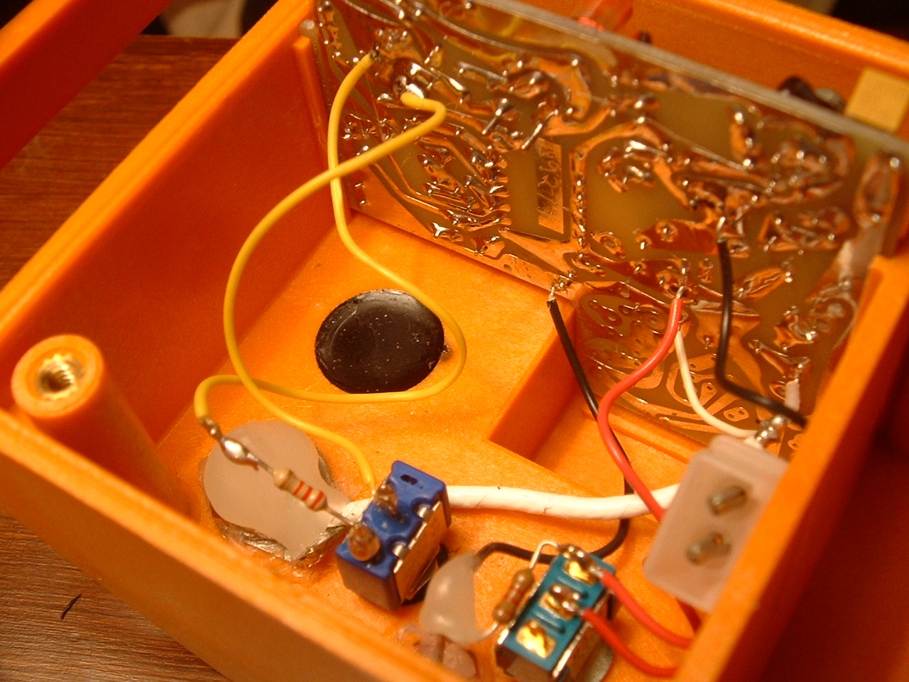 Step
9.
Finally,
solder the other ends of your wires to your switch.
Because of the increased current warning as annotated in the
circuit diagram, I also installed a 220 ohm resistor inline with
one of the shorting wires. This is optional, but may help
to save your battery. You can experiment with
different value resistors, but if you go too high the sweep will
not be inhibited. I found this to be the case at 1,000
ohms, but it will probably occur sooner and it also will
probably vary with the strength of your battery.
Step
9.
Finally,
solder the other ends of your wires to your switch.
Because of the increased current warning as annotated in the
circuit diagram, I also installed a 220 ohm resistor inline with
one of the shorting wires. This is optional, but may help
to save your battery. You can experiment with
different value resistors, but if you go too high the sweep will
not be inhibited. I found this to be the case at 1,000
ohms, but it will probably occur sooner and it also will
probably vary with the strength of your battery.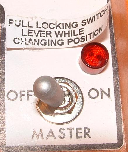 "PULL
LOCKING SWITCH LEVER WHILE CHANGING POSITION"
"PULL
LOCKING SWITCH LEVER WHILE CHANGING POSITION" 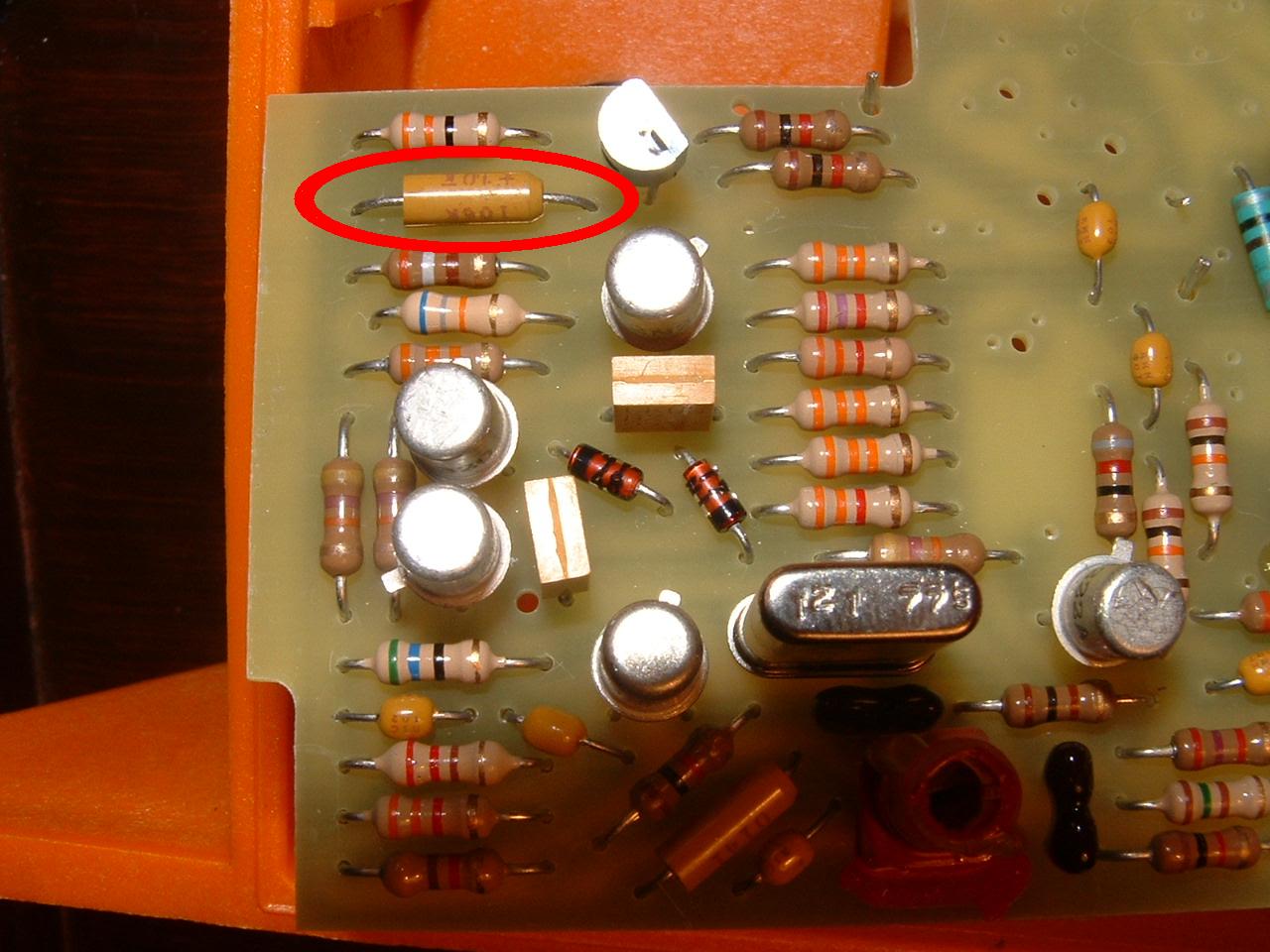 If
you short the capacitor shown here, your practice beacon will
transmit a single-tone that is moderately pitched in comparison
to the familiar sweep. This is different than the carrier
only sound, which sounds like "silence." A carrier only
signal sounds like someone has depressed a microphone on a
two-way radio but isn't saying anything. You get your
practice beacon to transmit carrier-only by performing
Modification #1 on this page.
If
you short the capacitor shown here, your practice beacon will
transmit a single-tone that is moderately pitched in comparison
to the familiar sweep. This is different than the carrier
only sound, which sounds like "silence." A carrier only
signal sounds like someone has depressed a microphone on a
two-way radio but isn't saying anything. You get your
practice beacon to transmit carrier-only by performing
Modification #1 on this page.