CONVENTIONAL GRID SYSTEM
![]()
![]()
![]()
![]()
![]()
![]()
![]()
![]()
|
|
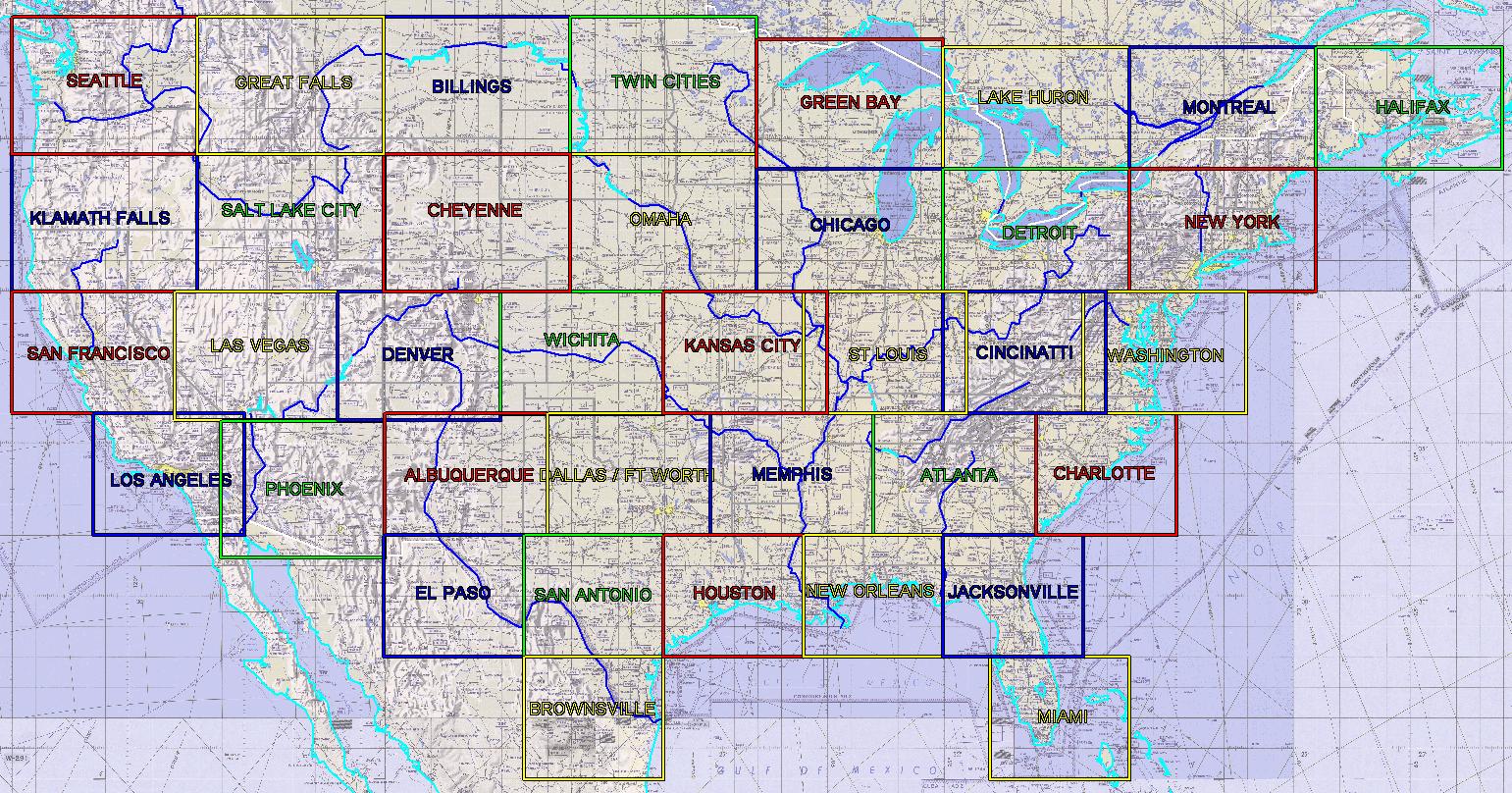
The Conventional Grid System remains one of Civil Air Patrol's lasting contributions to Search and Rescue. The CAP (Conventional) Grid system was originally developed in the early 1960s by CAP members in Washington State. It was soon adopted nationwide. The Conventional Grid System is not likely to disappear any time soon, despite some rumors to the contrary. In fact, the current United States National Search and Rescue Supplement to the International Aeronautical and Maritime Search and Rescue Manual (Appendix E), dated May 2000, includes information on the Conventional Gridding System. The basic premise of the Conventional Grid system is to divide the United States into 15-minute by 15-minute quadrangle grids. These grids are then numerically labeled sequentially on each sectional chart. The order of numbering is from the top left to the top right, down one row, and so on. Where there is overlap between sectionals, the westernmost sectional map is designated the primary. Gridding instructions below go into detail on the gridding method.
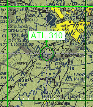
15-minute grids are further subdivided into 7.5-minute grids using the A - B - C - D method using the same scheme as in the Cell grid system. The small diagram to the left depicts how this may be done. Using this system allows CAP personnel to easily designate areas for search. For example, an operations director could say, "I would like Twin Cities (Sectional designator MSP) Grid 121 searched." Operations Personnel may further request the search method he or she desires in that grid, and may further restrict the search to a smaller area (e.g., MSP 121A). A tasking such as this positively identifies the region to be searched to anyone using the CAP grid system. Most current CAP publications do not include the grid system, although it has remained in the more-obscure National Search and Rescue Manual. Not wanting this information to be lost forever, the CAP ES Resources website has put all of the CAP grids online. To view the grids for a particular sectional map, navigate to the Gridded Sectionals page and click on the sectional of interest either by clicking on the map or on the tabulated list. You may want to hang up a gridded chart in a useful place such as your CAP hangar, FBO, or other common mission base. You may want to use wallpaper paste to attach the chart to the wall. It will then always be available for reference. See photo on the Gridded Sectionals page of a gridded sectional being used during the Steve Fossett search. It is not a bad idea to grid a chart that uses a larger scale, such as a WAC chart. You can use this chart as a reference to locate the area of interest and then fly it off of a sectional. In any case, you won't want to discard a gridded sectional once it goes out of date. While it can't be used for navigation, it can be used for reference--and the idea of re-gridding a new sectional chart every 6 months is not exciting. At worst, give your old gridded sectional to another CAP member who might make good use of it. You individual State's aeronautics division may have state aeronautical charts pre-printed with CAP grids. Consider writing them a letter to ask. Lieutenant Colonel Ray Andrews of Great Lakes Region Headquarters developed an aid to find the appropriate grid. This is a DOS executable file, circa 1989. It was originally intended for ELT missions to determine the grid of SARSAT hits. The program, called "GridFind," will take a set of latitude-longitude coordinates and determine the sectional and grid number within that sectional where the target is located. This program may also be used for many other applications such as DR and CD operations. A limited NAVAID and Airport database is also part of the program. It can be downloaded from this site via the downloads page.
Click on the map for a larger version.
How do I grid a sectional chart? The EASIEST way is to download and print it from the Gridded Sectionals page! If you'd like to grid your own sectional, it is a fairly easy but time consuming task. It definitely falls into the "arts and crafts" department. Due to the conical projection of a sectional chart, the lines of longitude are straight but latitude lines are slightly curved. It is possible to take a flexible yardstick and use a long piece of tape to bend the edge of the yardstick to match the latitude curve, thus facilitating easy drawing of lines. Every degree of latitude and longitude will yield 16 grids, or four lines per 1 degree by 1 degree square (technically, "quadrangle"). The 30 minute lines are already drawn, so the only additional lines necessary are those at the 15 minute marks. These are the difficult ones to draw and may require the yardstick technique listed above. You can also find gridding instructions in the old CAPR 55-1, 1 January 1992. It has gridding instructions in attachment 4 (pages 54 and 55). If you didn't throw that one out when CAPR 55-1 (dated 15 October 1998) replaced it, SAVE IT! I saved my OLD CAPM 50-15 (first published 1983) and have been very glad I did. It has been a treasure of knowledge that has since escaped us. You can download a .pdf copy of that old regulation here. THE FOLLOWING IS INFORMATION EXTRACTED FROM JOINT PUBLICATION 3-50.1, NATIONAL SEARCH AND RESCUE MANUAL (VOLUME II) A. The standard sectional aeronautical chart and the following grid identifications system is used by CAP when coordinating missions with the AFRCC and other agencies. CAP does not preclude the use of local procedures where they are deemed necessary or more practicable. Many missions are "local" in nature, and local procedures may be highly efficient and effective in the management of SAR resources within a defined geographical boundary. B. Standardized Sectional Aeronautical Chart Grid and Identification System
2. The basic 15 minute quadrangle (grid) is further broken down into quarter sections. The northwest quarter is labeled "A"; the northeast "B"; the southwest "C"; and the southeast "D". This breakdown is used when concentrated search is required and as a means of identifying 7 1/2 minute quadrangles, they need not be annotated on the charts but should be understood to exist and used in mission assignment and reporting. 3. Where charts overlap (the same grid is located on two or more charts) the grids on all charts will be assigned the number and identifier of the primary chart (the most westerly chart will be designated as the primary chart). Consider the Kansas City and St. Louis charts as an example. The Kansas City chart will be numbered in accordance with paragraph B.1. above; that portion of the St. Louis that is overlapped by the Kansas City chart will be labeled with the number identical to the same grid on the Kansas City chart preceded by the letters "MKC" to identify the origin of the grid numbers. (See the grid table below) The normal sequential numbers on the overlap area that are displaced by the primary chart will simply be omitted for use.
b. The Los Angeles chart has one (1) degree longitude overlap on the Phoenix chart within the area defined by 35-45N to 32-00N, and 116-00W to 115-00W. (Total of 60 grids) c. The Denver chart has a 15 minute latitude overlap on the Albuquerque chart within the area defined by 36-00N to 35-45N, and 109-00W to 104-00W. (Total of 12 grids) d. The Kansas City chart has one (1) degree longitude overlap on the St. Louis chart within the area defined by 40-00N to 36-00N, and 91-00W. (Total of 64 grids) e. The St. Louis chart has one (1) degree longitude overlap on the Cincinnati chart within the area defined by 40-00N to 36-00N, and 85-00W to 84-00W (Total of 64 grids) f. The Cincinnati chart has one (1) degree longitude overlap on the Washington chart within the area defined by 40-00N to 36-00N, and 79-00W to 78-00W. (Total of 64 grids) 4. Chart identifiers are listed in Table the grid table. 5. On charts with inserts over oceanic areas, number consecutively through the insert just as would be accomplished were the insert not published.
|
|||||||||||||||||||||||||||||||||||||||||||||||||||||||||||||||||||||||||||||||||||||||||||||||||||||||||||||||||||||||||||||||||||||||||||||||||||||||||||||||||||||||||||||||||||||||||||||||||||||||||||||||||||||||||||||||||||||||||||||||||||||||||||||||||||||||||||||||||||||||||||||||||||||||||||||||||||||||||||||||||||||||||||||||||||||||||||||||||||||||||||||||||||||||||||||||||||||||||||||||||||||||||||||||||||||||||||||||||||||||||||||||||||||||||||||||||||||||||||||||||||||||||||||||||||||||||||||||||||||||||||||||||||||||||||||||||||||||||||||||||||||||||||||||||||||||||||||||||||||||||||||||||||||||||||||||||||||||||||||||||||||||||||||||||||||||||||||||||||||||||||||||||||||||||||||||||||||||||||||||||||||||||||||||||||||||||||||||||||||||||||||||||||||||
This page of the CAP Emergency Services Resources™ website was last updated 07/01/2008
©1998 - 2007 Scott E. Lanis. All Rights Reserved.
 A
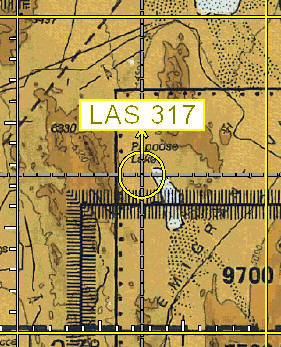
derivative of the Conventional Grid system is the Uniform Mapping
System, or UMS. UMS is seldom used today as other coordinate
systems such as latitude-longitude or UTM (universal transverse mercator)
have superseded UMS as they are much more accurate. The Uniform
Mapping System measures a location within a 7.5' subgrid by measuring
horizontally then vertically from the lower right corner of the subgrid.
This corner also exactly corresponds with the lower right corner of a
1:24,000 USGS topographic map. Units of measure are nautical miles
(NM). Most non-aeronautical charts will not depict a nautical mile
in the scale, but it can be easily determined as one minute of latitude
(minutes North) is equal to one nautical mile. These measurements
are then added to the end of the grid designation. For example,
locate the"G" in "EMIGRANT"
of grid LAS 317D at left. That G is 3.1 NM west of the southeast
corner of LAS 317D, and 3.9 NM north of the southeast corner.
Thus, using the Uniform Mapping System, that location is LAS 317D 3139.
Note that the decimal points have been dropped and the numbers entered
together. As a second example, locate LAS 317A 0614. You
will find that it is the "P" in
Papoose Lake. Notice that the locations
described in UMS will be, at best, only within 1/10 of a Nautical mile.
A Future version of
A
derivative of the Conventional Grid system is the Uniform Mapping
System, or UMS. UMS is seldom used today as other coordinate
systems such as latitude-longitude or UTM (universal transverse mercator)
have superseded UMS as they are much more accurate. The Uniform
Mapping System measures a location within a 7.5' subgrid by measuring
horizontally then vertically from the lower right corner of the subgrid.
This corner also exactly corresponds with the lower right corner of a
1:24,000 USGS topographic map. Units of measure are nautical miles
(NM). Most non-aeronautical charts will not depict a nautical mile
in the scale, but it can be easily determined as one minute of latitude
(minutes North) is equal to one nautical mile. These measurements
are then added to the end of the grid designation. For example,
locate the"G" in "EMIGRANT"
of grid LAS 317D at left. That G is 3.1 NM west of the southeast
corner of LAS 317D, and 3.9 NM north of the southeast corner.
Thus, using the Uniform Mapping System, that location is LAS 317D 3139.
Note that the decimal points have been dropped and the numbers entered
together. As a second example, locate LAS 317A 0614. You
will find that it is the "P" in
Papoose Lake. Notice that the locations
described in UMS will be, at best, only within 1/10 of a Nautical mile.
A Future version of